FIBERSIM
Live Webinar: Leveraging Parasolid Part Data for Composite Manufacturing in Fibersim
July 12, 2023 2:00 PM EST
Join SDA Engineer Dylan Smith live on June 22nd to learn how to import your data from software like Siemens NX and Solidworks into Fibersim, the industry standard software for composites, in this free webinar.
- Open Solidworks files directly in NX
- Prepare model geometry in NX
- Create Fibersim laminate data
- Receive part revisions due to design changes
- Import new models
- Update changed features in Fibersim
- Export offset surface and compare with original model
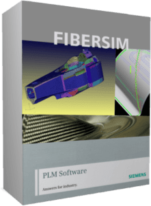
Fibersim software is a powerful add-in for NX, Pro/E, and Catia. It greatly simplifies the task of design, analysis, and manufacture of composite parts by giving engineers the tools to easily modify, update, and iterate on composite designs. This allows the engineer to work with combinations of material types, fiber orientations, stack-up orders, balance, symmetry, drop-offs, splices, and dart definitions.
The add-in integrates this large set of attributes into the design by automatically creating ply-geometry, assessing ply-level profitability, and providing excellent exchange of analysis and manufacturing data.
Case Study: Lotus F1 Team
Fibersim Configurations
Fibersim Pro
Main Capabilities:
- Ply Based Design
- Multi-Ply Based Design
- Producibility Simulation
- Parametric Surface Offset
Function:
- Manual ply design
- Specification driven automated ply design
- Simulation- hand lay-up, automated lay-up, forming ply shift
- Tools for making a manufacturable design – splicing, darting
- Parametric Surface Offset – automated IML surface/solid creation
Value:
- Increase production development efficiency
- Increase efficiency and reduce errors during design change processes
- Reduce product cost by identifying performance and production issues up front
Fibersim Elite
Main capabilities:
- Ply Based Design
- Multi-Ply Based Design
- Zone/Grid Design
- Volume Fill
- Wind Blade Design
- Producibility Simulation
- Parametric Surface Offset
Function:
- Manual ply design
- Specification driven automated ply, zone, thick part and wind blade design
- Simulation – hand lay-up, automated lay-up, forming ply shift
- Tools for making a manufacturable design – splicing, darting
- Parametric Surface Offset – automated IML surface/solid creation
Value:
- Increase product development efficiency
- Increase efficiency and reduce errors during design change processes
- Reduce production cost by identifying performance and production issues up front.
Features
Engineers who design and manufacture composite parts face the time-consuming and difficult process of creating or exporting flat patterns to nesting software for use in automated cutting systems. Without an automated way of creating flat patterns and exporting them from the CAD model, engineers often find that their flat patterns are inaccurate.
With the Flat Pattern Export module in the Fibersim portfolio, engineers can automatically generate flat pattern data files for export from their CAD workstation directly to common commercial nesting systems. The module maintains file integrity by including attributes such as ply name, sequence, material specification, and orientation, eliminating the need for manual manipulation of drawings and patterns. As a result, the module increases engineering efficiency and manufacturing productivity while achieving more accurate flat patterns and less material waste.
The Laser Projection module in the Fibersim portfolio helps engineers capitalize on the power and accuracy of today’s laser projection machines for manufacturing and inspecting products made of advanced composite materials. Laser projection systems can reduce errors and shorten the layup time for composite parts by displaying ply outlines directly on the layup tool. The laser outlines aid in the location and orientation of plies during the layup process. However, creating data files to drive laser systems is tedious, time-consuming and error-prone.
With the Fibersim Laser Projection module, engineers can automatically generate laser data files from within their CAD system directly from the 3D model of the composite part for both layup and inspection. Automated ply verification can help ensure that parts meet specifications during the layup process by checking material, orientation, ply edge, and detecting foreign objects as each ply is laid down.
The Tape Laying Interface module in the Fibersim portfolio enables engineers to generate and export design data directly to automated tape laying machines for manufacturing composite products and parts. Tape laying machines combine the advantages of contour tape laying and computer control to automate the manufacture of complex composite parts that conventionally require extensive hand lay-up. Creating the data to drive tape laying machines has traditionally been error-prone and tedious, but the use of these machines can dramatically reduce cycle times, cost and manual rework of physical composite plies.
With the Tape Laying Interface module, engineers can automatically generate tape laying data files within their CAD system directly from the 3D model of a composite part. This eliminates errors, significantly increases engineering productivity and makes it easy to accommodate changes and optimize designs.
Tape laying machines bring the advantages of laying long courses of pre-impregnated unidirectional tape and high-speed computer control to automate the production of relatively flat composite parts that conventionally require extensive hand layup. Using tape laying machines can reduce costs, scrap rates and structural weights while increasing production rates when manufacturing composite parts. However, creating the data files to generate the path planning that drives the machines is tedious, time-consuming and error-prone.
With the Fibersim automated tape laying (ATL) Interface software from Siemens PLM Software, you can automatically generate native format data files for use with path planning from within the composite CAD model. This significantly increases engineering productivity, eliminates errors, and makes it easy to accommodate changes and to optimize designs for automated tape laying. ATL supports NX software, Catia V5, PTC Creo and PTC ProEngineer.
The automated tape laying interface uses the composite engineering definition to generate the import files for path planning software used to program the automated tape laying machine. The composite data and the unique tape laying entities include:
- Tool and intermediate simulation surfaces
- Ply boundary/hole, orientation angle, fiber direction curves, material and layup start points
- Feed rate and pressure process regions
- Material scrap areas
Machine alignment methods - Trim definitions for flat parts or blanks, including contours and holes
- Fibersim ADD features – ramped part boundaries (EOP), bird beaks, bat ears and staggered origins
Fiber placement machines combine the advantages of filament winding, contour tape laying, and computer control to automate the production of complex composite parts that conventionally require extensive hand layup. Fiber placement machines can reduce costs, cycle times, and manual rework of physical composite plies, but creating data to drive these machines has traditionally been tedious and error-prone.
With the Fiber Placement Interface module in the Fibersim portfolio, engineers can automatically generate fiber placement data files within their CAD software systems directly from the 3D model of a composite part. This significantly increases engineering productivity, eliminates errors, and makes it easy to accommodate changes and optimize designs.
FiberSIM Webinar

See how the world's first carbon-neutral spaceflight experience company is revolutionizing space travel.
Advanced Support
Receive advanced support from engineers that use Fibersim every day.
SDA Software is more than a premier value added reseller of Fibersim. We employ award winning engineers that use it every day as part of our professional consulting services. We have the capacity to provide advanced technical support and consulting services to our customers.
Our standard support is included when you purchase a product license or subscription (active maintenance). This covers the following:
- Licensing and setup questions
- Basic technical questions about software features and building models
- Simple troubleshooting.
We understand that for particularly challenging issues more advanced support is required. For this, we also offer advanced support services, which include:
- Detailed help building complex models (even production simulations)
- Extensive troubleshooting, debugging, and testing of models
- Custom consulting projects.
Advanced support is not included with active maintenance.
Meet Dylan Smith, one of our expert engineers
